tech.jpg)
In a previous post I wrote about the Indivision AGA MK3 and how it allowed me to use my old Amiga 1200 with a modern flat panel monitor. The post described the image quality produced but was lacking on details on how the Indivision was actually mounted in my system. The reason for this lack of information was that I had at the time not decided on how and where I was going to mount the Indivision's little board with the video connectors.
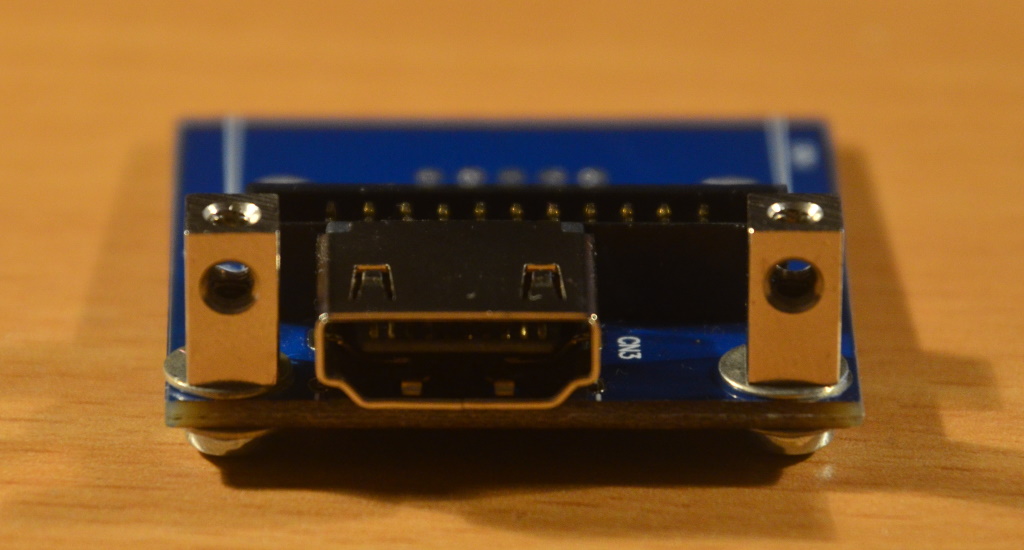
The video output board of the Indivision is connected to the Indivision itself by means of a flat-cable.This flat-cable is long enough to allow the video board to be mounted almost anywhere inside the Amiga 1200. The video board has two video connectors on it, which allows the owner to either use a VGA cable or a HDMI type cable to connect the Amiga with a monitor. The connectors are mounted at opposite ends of the little board, so you just let the required connector stick its head out of the Amiga case. The little board as shown below:
The manufacturer (Individual computers) suggests for Amiga 1200 owners to use the blanking plate that is next to the mouse / joystick ports of the Amiga. For this purpose they have included screws that allow it to be fixed in that exact position. Unfortunately in my 1200 that position is already in use by a CF-card slot that is connected to the internal IDE connector. This allows me to easily change the CF-card that is used by the 1200 as its hard drive. Having that card easily accessible allows me to quickly boot a different Workbench version and also to make backups of each CF card by creating a full disk image using my PC's CF-card reader. That is functionality I was not planning to give up.
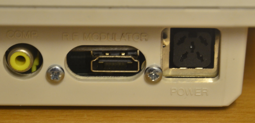
On the support forum for the Indivision I learned that a couple of owners had removed the RF modulator from the 1200's main board and used its now vacant hole to mount the VGA connector. This did require some changes to the shape of the hole, but mounting the VGA connector itself is fairly simple thanks to its two jack posts.The HDMI connector does not have such fixings, which makes mounting the video board with the HDMI out less straight forward.
Having said that, when the video board is mounted upside down the HDMI connector will stick out of RF the modulator hole without any modification to the hole required. The fact that the connector is offset from the middle of the board is really helpful here. Nice attention to detail by the designers.
Removing the RF modulator from the Amiga's main board is not a difficult job when you're a bit handy with a soldering iron. It is only held on to the main board by a few leads and there are no big blobs of solder that fix the metal box of the modulator to the board. The RF modulator works fine with old analogue tube TVs, but modern flat panel TVs won't produce a useful image from it. I've never used mine on the 1200 and am therefore happy to go without.
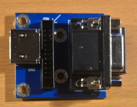
The solution I found to mount the board securely to the back of the Amiga is the Ettinger 05.60.223 stand-off. Each stand-off mounts to the PCB via an M2.5 screw (and a top and bottom washer to spread the strain) and provides a threaded M3 hole which allows the PCB to be mounted upside down against the back of the case of the 1200. The image below shows the little video board with the two stand-offs in place:
You may also notice that the VGA connector is missing from the board in the above image. Mounting the PCB with the HDMI connector sticking out of the back means that the VGA connector will be pushing against a couple of electrolytic capacitors on the Amiga's main board. To make things worse there is also the flat-cable that needs an exit from the video PCB, past the VGA connector and to the main board of the Indivision. This all got a bit too cramped, so I decided to de-solder the VGA connector completely. Now there is no pushing against the caps and there is ample space for the flat-cable to make its way out of there as can be seen below in the image showing all three PCBs that make up the Indivision.
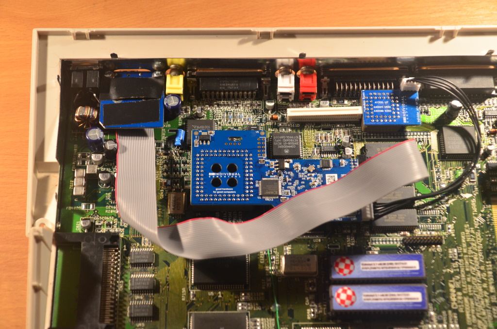
The larger blue board is the Indivision AGA MK3 main board. It sits on top of the custom chip named "Lisa", which is in charge of the video output.The little blue board on the right sits on top of one of the CIA's so it can detect keyboard presses. In the top left corner, with the flat-cable sticking out, is the little video board. It is mounted upside down in a space created by removing the RF modulator.
Mounted this way the video connector feels really solid. There is no movement when inserting or removing a HDMI cable. Since there is also ample space between the little video board and the metal shield above it I removed the electrical tape that is visible on the image above.