 tech.jpg)
This post describes a bit of the design process that went into the creation of BassMX. If you arrived here via a search and simply want to know what BassMX is all about, then please head on to this post, which describes its functionality.
The idea
The basic idea of mixing the bass for both channels came to me many years ago. I was listening to a colleague who had setup a Bose Acoustimass system, comprising of two small speakers and one larger subwoofer box. He explained how impressed he was and that it really seemed is if it was just the little speakers that filled the room with sound.
With the Acoustimass system a single subwoofer takes care of the low frequencies for both channels, while two small speakers provide the mid and high frequencies and with those the stereo image of the audio. Similar to how a modern surround setup uses a big subwoofer, but at that time the idea of a subwoofer was quite new to most consumers.
This was when the idea of taking the low frequencies and mixing them occurred to me for the first time. But unlike the single subwoofer, I wanted to feed the low frequencies back to both channels, so that both speakers of a standard stereo setup would produce the same low frequencies while the mid to high frequencies would be unaffected.
To be honest, the idea came as some kind of quick insight and at the time I did not intend to actually do anything with it. Life moved on and years passed without me thinking about it. When I did again think about it I had just started writing my first book, which took all my spare time, followed by the second book, which did the same. After taking a large number of months of just using my Amiga for fun I decided to look into this "mixing the bass" idea and see where it'd take me.
The proof
Before designing the hardware and spending my hard earned cash on something that may not work at all I decided to see if the idea had any legs to begin with. For this I recorded the sound of a couple of demos running on my Amiga 1200 into Audacity on my PC. I then copied the recorded track into another track and low-pass filtered the copy. Then I swapped the left and right channels of the copy and mixed it back into the original recording.
The result made me happy as it sounded rather good, especially at the louder volumes. This proved to me that the idea actually worked and therefore was worth designing hardware for.
The goals
At the beginning of the design process I set some goals that the resulting design should meet. Some of these goals are technical while others are more practical in nature. The list I ended up with is as follows:
- Don't design it specifically for the Amiga, allow for other uses.
- Do not change the nature of the sound of the Amiga.
- 5V supply so it can use an old phone charger or one of the Amiga's ports.
- Less than 10mA current draw in case the Amiga's parallel port is used for power.
- No screw terminals, proper connectors.
- Keep it simple. Use analogue parts instead of DSPs.
- Easy to obtain components (e.g. no exotic chips that are hard to get).
- Easy to solder for less experienced people (no surface mount devices).
For the first goal I have no clue what the "other uses" could be. But if there is another vintage (computer) system out there that can benefit from something like BassMX then I'd like that system to be able to use BassMX as-is, without any pre-amps or other additional devices.
The low-pass filter
The main functionality of the design depends on a filter that lets only the low frequencies through. This type of filter is known as a low-pass filter. An ideal low-pass filter lets all frequencies through up to the cut-off frequency and anything higher than this cut-off won't get through at all.
Unfortunately these ideal filters do not exist in the real world. Real low-pass filters start filtering a little bit around the cut-off frequency and filter more and more the higher the frequency gets. This creates a grey area after the cut-off frequency where higher frequencies still leak through, albeit at an increasingly lower volume. This grey area can be made smaller by increasing the "order" of the filter - for analogue filters increasing the order means adding more components and thus more cost.
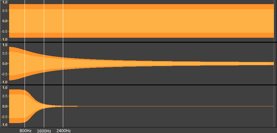
The graph above shows the difference between a 1st order filter (middle waveform) and a 4th order filter (bottom waveform). The top waveform is the original audio, which in this case is a linear frequency sweep from 10Hz to 10kHz. Both filters have been setup as a low-pass with their cut-off frequency at 800Hz.
At 1600Hz, twice the cut-off frequency, the first order filter is still passing the audio at half the original level while the fourth order filter passes only a very small amount. Even at the end of the sweep, at 10kHz, there is still audio being passed by the first order filter. The amount of audio passed by the fourth order filter starts to become negligible around 2400Hz.
A sixth or eight order filter would pass even less signal past the cut-off frequency, but for this application a fourth order filter looks sufficient, which is what I ended up implementing.
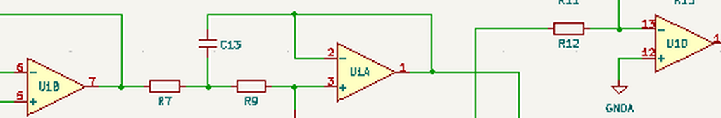
Finalising the design
From the goals (analogue only) I knew that the design was going to be using opamps for the mixing and filtering. It was just a matter of finding out how many. The 4th order low-pass filter requires 2 opamps and the mixing stage requires another. The low-pass filter is sensitive to the impedance of the source that is connected to its input. In other words, the actual cut-off frequency can be influenced by whatever is connected to the input of the filter. To alleviate this I added an input stage to the design, which ensures that the impedance at the filter's input will always be the same. This input stage requires one opamp as well, bringing the total for each channel to 4. This works out well since it is quite common to have four opamps in one single integrated circuit case.
Simulating the design
The last step before ordering components and building the prototype is to try the design out in a circuit simulator. Initially I had planned to use the Amiga version of Spice to do this, but it has been such a long time since I've used a text based version of Spice that I found that I had to relearn everything. That was going to take too much time, so instead I used LTSpice, a graphical version of Spice that is maintained by the semiconductor manufacturer Analog devices. I may come back to Amiga's version of Spice some time in the future, though.
After creating the hardware design in LTSpice I gave it a 1kHz tone on the left input and a 250Hz tone on the right input. Then I simulated the signal coming out of the left output, of which a screenshot is shown below:
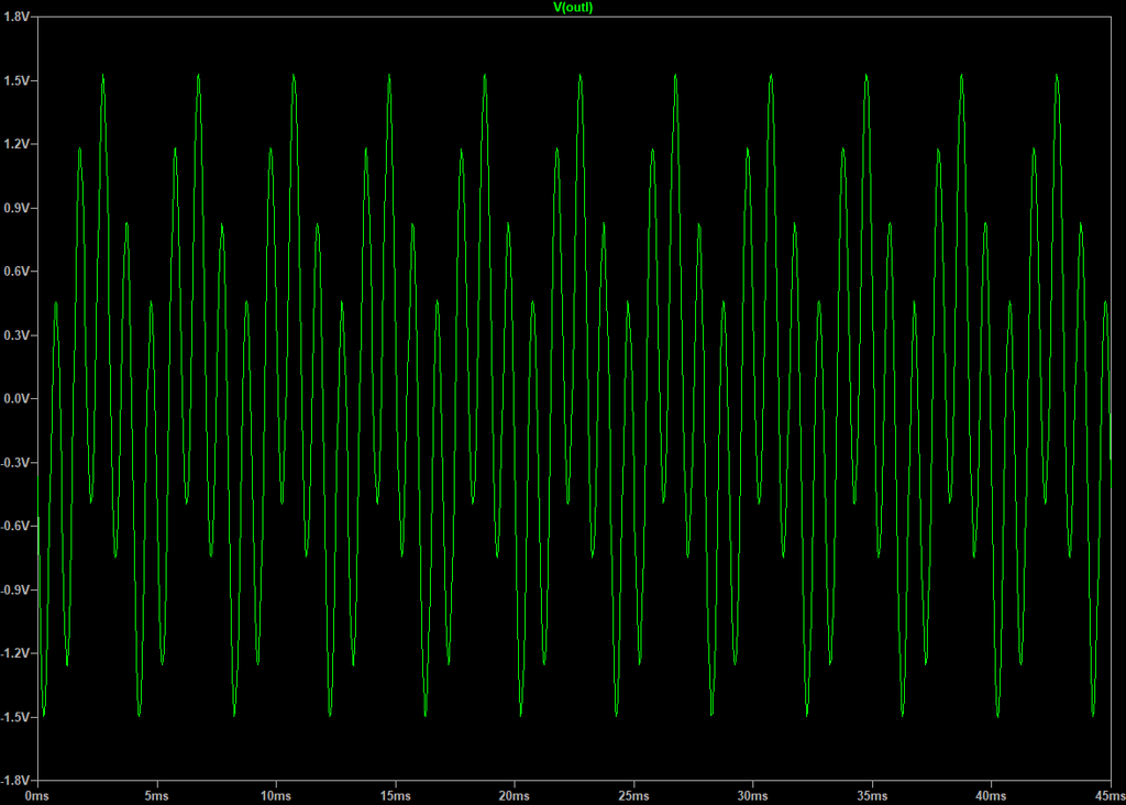
The signal is exactly as I expected, the 250Hz tone of the right input has been mixed with the 1kHz that was already present on the left input. I then changed the tone on the right input to 5kHz and then the left output only contained the 1kHz tone. Exactly as it should.
Building the prototype
With the simulation proving that the design is (at least theoretically) functional I could now build a prototype with more confidence in a positive end result. For the prototype I did not design a proper circuit board yet, but instead I build it on some perfboard.
Unfortunately the prototype only worked for about 50%. When applying a signal to the left input I could hear the same signal on the left output and a low-pass filtered version of it on the right output. However, there was something going wrong with the right input. Any signal on the right input sounded heavily distorted on the right output and barely registered on the left output.
This was quite likely due to a wiring fault somewhere on the right channel, but after looking at it for a while I gave up trying to find it. Since the one channel worked fine I took this as proof that the design as such worked as intended, even though the prototype did not, and moved on to creating the PCB.
Creating the PCB
There is ancient PCB design software for the Amiga, but I have never used it. Instead I have been using the KiCad package for quite a number of years and can really recommend it. Yes, it has its own idiosyncrasies, like all CAD packages do, but I find that for me the package does not get in the way of the design process.
KiCad also includes a program that can take an image file and convert that to an object that can be used on the PCB. In my case I used it to create the arrows on the back of the PCB that visualise how the audio signals get routed.
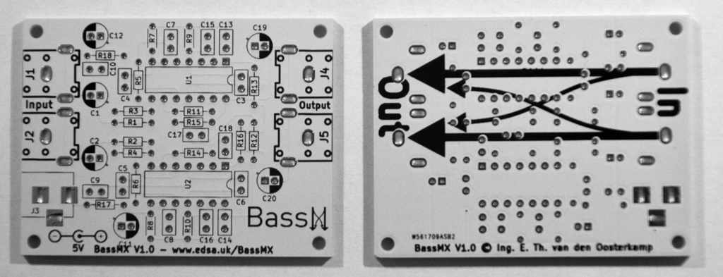
When I saw the arrow design for the back of the PCB I thought that if I turned it so that the arrows pointed down it would make a nice logo as well. I then used it to create the BassMX graphic that is placed on the component side of the PCB.
When I was happy with the design of the PCB I used the KiCad plotting tool to create the Gerber files and then sent these off to PCBWay so they could manufacture the boards.
Building the first one
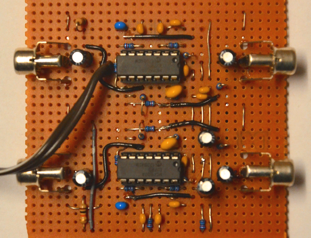
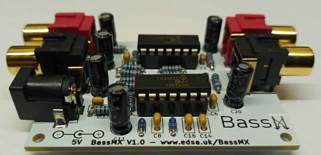
To build the first one I only ordered a small amount of parts and used up some parts I still had in my parts bin from previous projects. This is why it ended up with gold coloured RCA connectors instead of the more standard chrome coloured ones. I also usually prefer to use white/red instead of black/red, which is what the final version will use.
To make possible future fault finding easier I placed the two integrated circuits in sockets. If necessary this allows me to take the opamps out of the circuit to make measurements without the opamps affecting them.
In the end I was quite chuffed with the way it turned out as shown in the photo below.
Running the first tests
Since the prototype was only semi-working I was still quite apprehensive about the final design. Luckily on the first test this first one worked fine and I set out to play a number of different mod files through it to check out the effect. While it was working as intended I found the effect to be a bit too subtle. On this first board I used a cut-off frequency of 400Hz so I decided to create a second board but this time with a cut-off frequency at 800Hz. This proved to be the exact effect I was looking for, so I decided to use an 800Hz cut-off for all future boards. This second board is also what I used to create the comparison audio files that can be downloaded from the main BassMX page.
The current draw is on average about 1.8mA, which is well below the maximum of 10mA that I set as one of the requirements. This allows it to be powered from the parallel port safely.
Now what is this noise?
During my tests and recordings I was using one of the USB ports of my PC to provide the 5V for the BassMX board. There was a slight whine audible in the distance when I opened the volume on my amplifier to ridiculous levels, but that did not bother me since any normal audio at those volume levels would be instantly damaging to my speakers. However, when I used a cheap phone charger to power the BassMX board there was a clear digital noise, audible even at a moderate volume level, which I was not happy with.
As a test I gathered a number of USB power supplies and phone chargers and found that the result was hit and miss, but more miss than hit unfortunately - meaning that the V1.0 incarnation of BassMX is very susceptible to power supply noise. Considerably more than I'm happy with. A third board with considerably larger capacitors in the power supply section did fare slightly better, but still not good enough to my taste.
No worries, I've got a couple of tricks on my sleeve for this kind of issue. Just a shame that I need to make new PCBs for this change.. I'm working on an V1.1 version that will not have this issue and I'll post a new article soon with an update on the progress.
So quite unexpectedly: to be continued...