 tech.jpg)
In a previous post I described the initial design process of BassMX, this post continues from there and describes the improvements made to create the final version. If you arrived here via a search and simply want to know what BassMX is all about, then please head on to this post, which describes its functionality.
The issue
What I found was that the original design was quite sensitive to noise coming from the power supply. Some power supplies were noisier than others and some weren't noisy at all. It was not really possible to predict which ones would be noisy and which ones wouldn't, so I could not just provide some specifications for the power supply used and then expect all supplies meeting those specifications to actually be quiet.
In the end I want BassMX users to be able to just use any power supply without having to deal with noise issues. And for this to be possible I needed BassMX to sufficiently clean the noise from the incoming power. I was also keen to ensure that BassMX would continue to work with a 5V supply and that the current draw was kept below 10mA.
For testing I picked the most noisy supply I had found and used it to try various methods of power cleaning to see if I could get the audio output of BassMX quiet.
The passive method
Of course the first thing I tried was to simply throw some large capacitors at it. But even with two low ESR 1000uF capacitors the noise was still there. Much reduced, mind, but very obviously still there. This was not my preferred solution anyway since large capacitors do take a lot of space on the board, which I was trying to keep small.
As a second passive option I designed an actual filter for the power supply using a ferrite bead inductor and a couple of smaller capacitors.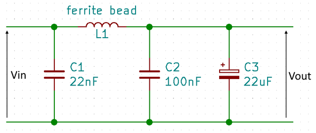
The impedance of the ferrite bead (L1) goes up when the frequency goes up, making it more difficult for higher frequencies to pass. At the same time the impedance of the capacitors (C1 to C3) goes down when the frequency goes up, causing these frequencies to be shortened to ground. Combining these two effects creates a low-pass filter where DC passes easily, but noise passes with difficulty. Since there is no impact on DC, the output voltage will still be the same as the input voltage (ignoring losses in L1).
For some of the power supplies this was enough to clean the output more than "good enough", but for the bad noisy power supply I used for testing it was really not enough at all.
Reassessment
From this I concluded that passive methods do not cut it, so I needed to look out for an active method of cleaning the power supply voltage. The downside of an active solution is that the current draw goes up and that the resulting clean voltage will be lower than the supplied noisy voltage. I therefore needed to see how low I could go before the supply voltage would be too low for BassMX to operate properly.
The only components requiring a power supply on BassMX are the opamps. The ones I selected can be powered with as little as 1.8V and provide rail-to-rail output. Rail-to-rail means that the full power supply voltage is available to the audio signal. For example when using a 5V power supply there will be 2.5V available for the positive half of the audio and another 2.5V available for the negative half of the audio.
The lowest still suitable supply voltage therefore also depends on the voltage swing of the audio signal that BassMX is processing. To look at this in real life I fired up my Amiga 1200 and made it play a 500Hz tone on both outputs. I'm using a frequency below the filter cut-off and play the same signal on both outputs to ensure I get to see the highest (mix) level on the output of BassMX. I then used my trusty old oscilloscope to measure the signal levels. The image below shows the input level (left) and the output level (right):
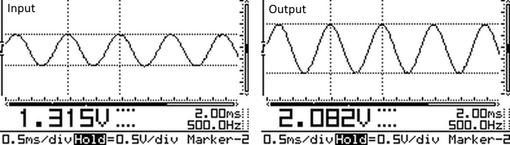
The scope shows that the input signal has a swing of about 1.3V, while the output signal is louder and has a swing of almost 2.1V. Yes, this method is not very accurate, but does give us a good general indication of what the levels are. We now know that we can take a power supply of 2.5V as the safe minimum and still have another 2.5V left of the original 5V to use for the active cleaning.
The active method
The Zener diode is a special kind of diode that tries to maintain a fixed voltage over itself. A resistor is used to limit the current through the Zener diode. This current is typically about 20mA since that is the region where the Zener's voltage is less sensitive to current variations. That is too much current for BassMX - I'd like the power cleaner to use no more than 1mA at a 5V input. Using a current that low makes the Zener's actual voltage a bit higher and vary more with component variations but for BassMX this does not matter; the actual voltage is less important as long as it is free of noise.
In a circuit where only the Zener and its current limiting resistor are used all the current that supplies the rest of the circuit will also flow through this current limiting resistor. In our case the current through the Zener (< 1mA) will be less than the current through the BassMX (1.6mA). This will cause the voltage supplying BassMX to vary when the current drawn by BassMX varies, which is not a good thing. The solution to this is to add a transistor. Now the current that supplies the rest of BassMX will go through the transistor instead of the Zener's current limiting resistor. The circuit with the transistor and the Zener diode looks as follows:
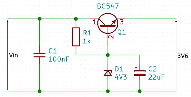
The voltage over the Zener diode (D1) will be 4.3V, the transistor (Q1) will try to maintain a voltage of 0.7V between base (pin 2) and emitter (pin 3). This causes the output voltage of the circuit to be 3.6V, which is more than enough to make BassMX work. The output voltage is also independent of the input voltage (as long as the input voltage is high enough). This is an added bonus that will allow BassMX to accept not just 5V but a range of input voltages. Capacitor C2 has been added to filter away noise from the base of the transistor thus helping to keep the voltage clean.
In the circuit above resistor R1 is the current limiting resistor. It feeds the Zener diode as well as the transistor's base - although the current into the base of the transistor is so small that it is negligible. When Vin is 5V the current through R1 and the Zener will be 0.7mA. With a Vin of 12V the current through R1 and the Zener will be 7.7mA, dissipating approximately 60mW in R1. That is still low enough when using a 1/8th Watt (125mW) resistor for R1.
Trying it out
Since it is such a simple circuit I first tried it out on a breadboard. When this proved to be successful I made a small perfboard version, which is shown in the photo below.
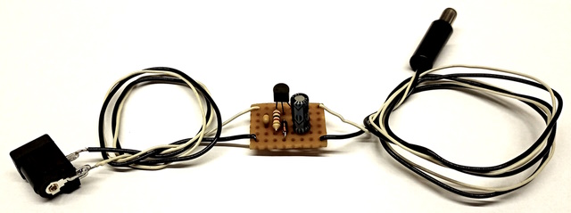
This just works by plugging it between a V1.0 BassMX module and the power supply and as such allowed me to try out various power supplies and listen to the BassMX output to check for any noise on the output.
And indeed it "just worked". No noise on any of the power supplies at any volume level. Quiet like I intended it to be. To check everything was indeed alright I also measured the total current draw while playing some mod files and this varied between 2.4 to 2.5 mA with the odd peak nearly getting to 2.7mA. This fits with my goal of keeping it below 10mA at 5V.
Another method
Before settling on the Zener and transistor method I described above, I also had a look at using a 3.3V fixed voltage regulator. Finding a suitable regulator proved more difficult than I had expected. Most of them are surface mounted devices, which I did not want to use for this project, and then there were plenty that needed more than 5V to work. The few that were through hole mount and accepted 5V as well as voltages up to 12V were quite bulky and expensive compared to the Zener and transistor solution. A solution using an adjustable voltage regulator did not fare any better; that was also more expensive and required more board space than the transistor and Zener solution.
The new PCB
As a last test I removed some of the passive filtering that was part of the V1.0 board power design. This power filtering obviously did not do its job, but I wanted to be sure that removing it would not start a different hum all together. Removing it made no difference to the quietness of the output, so I decided to remove it from the V1.1 version of the board.
Since this is the last redesign I hope to have to do for BassMX I'm going through every single component to see also what the cost implications are for the selected type. Below I have posted a screenshot from KiCad's 3D viewer showing the current state of the new design.
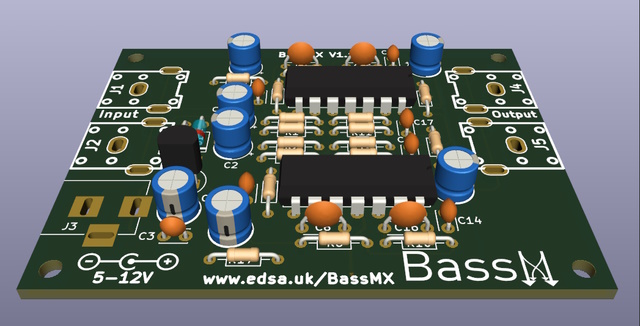
This should be finished in a couple of days and then I can get the PCBs made. As soon as I've got them back from the manufacturer I will build my first V1.1 BassMX and to celebrate that I'll post another article here on the blog.
And by then I also hope to have sussed out how to get these lovely BassMX modules in the hands of my fellow Amigans to play with and enjoy... Stay tuned, as they say.